Saturday, November 26, 2011

Tail Light Panel and Trunk Floor – Part 5: Left Coilover Mount & Trunk Floor Install

I am happy to report; the left trunk floor is complete!  And I would be remiss if I failed to mention that the NPD-supplied trunk floor panel was another excellent piece that required no modification short of trimming the lower edge of the drop-off (which is desirable and expected anyway.

To begin this phase of work, I decided the time was right to install the left rear coilover mounting bracket included in the Heidts 4-link suspension kit I am installing in my car.  Under normal circumstances, this mount would be a bit tricky to weld in place with a complete trunk floor.  However, since the trunk floor was completely out of the way, I decided to install this mount while the opportunity was ripe.

I started by running the bracket through my blast cabinet to clean off the mill scale and slight surface rust that had developed on the surface.  Then, I treated the bracket with a dose of phosphoric acid to clean and etch the metal.  After a few hours of dry time, I clamped the bracket into place per the instructions included with the Heidts kit.  With all measurements verified, I clamped the bracket solidly into place, saddling the lower frame rail and welded it into place.  The lack of a trunk floor panel made welding the inside edges of the bracket quite easy.  The job of welding the inner edges of the bracket would have been nearly impossible with the trunk floor in place.

Next came the trial fit of the trunk floor itself.  I tend to spend a lot of time getting repair panels to fit as close to perfect as I can.  As a pleasant surprise, the trunk floor panel fit amazingly well straight out of the box.  I started by dollying the flange that meets the inner wheel house until the fit was just right and the panel would seat firmly against the inner wheel house.  Then I aligned the rear of the panel with the frame rail and clamped it into place.  After a few small adjustments, I was ready to mark the location of the frame rail flanges on the panel so I could drill spot weld holes where required.  At the same time, I clamped and marked the lower quarter flange edge so it could be trimmed for a perfect fit.  With the panel marked, I marked each spot weld hole with my trusty paint marker and began punching and drilling the necessary holes.

I treated the bare metal flanges to a thin coat of SEM weld-thru primer (won’t be doing this again) and let it dry.  Next time, I will mask the individual spot weld areas to prevent any primer from coating these surfaces.  In my experience, the welds are much cleaner and easier to make without any such weld-thru primer in the way.  Lesson learned.

Using my painted reference outlines for alignment, I clamped the drilled panel into place and carefully adjusted its position until the fit was perfect.  Then, in my usual “clamp-the-hell-out-of-it” fashion, I clamped every flange as much as I could to bring every surface together as tightly as possible.  Particular attention was paid to the inner wheel house flange as this proved the most difficult flange to get fitting properly.  In the end, every flange fit exceptionally well and I was set to weld.

About an hour later, the left trunk floor panel was fully welded into place and looking like it was made to be there.  About another hour and a half of careful grinding, and all the welds were smooth and the repair was complete!  This pretty much wraps up the left rear corner repairs on the car and now I will move the whole operation over to the right side for a series of repair operations that will be virtually identical to what I’ve done on the left side.  Feels good!
Heidt's coilover bracket fresh out of the blast cabinet.

A good coating of phosphoric acid will be a good prep before installation.

This gives you an idea how accessible the bracket is without the trunk floor panel in the way.  Even these welding clamps would not have been able to be used in this way if the trunk floor was in place.

Coilover bracket welded in place on the outboard side.

And the inboard welds can be seen here.  Note the top weld and the curl around the corner.  These welds would simply not have been possible without this kind of access.

Fitting the trunk floor panel was remarkably easy.  A little flange work at the wheel house and some small adjustments at the rear and the panel fit was excellent.

Here, you can see that I traced around every flange to give me reference marks for drilling spot weld holes and to help me realign the panel when it comes time to clamp it in place for final welding.

The NPD trunk floors have extra material on the lower drop-off flanges to allow you to fit the panel perfectly to the lower quarter flange shape.  If you look closely, you can see this flange has been marked for trimming.

I coated the flanges with a light coat of SEM weld-thru primer.  I believe it would have been better to mask each spot weld location to leave it in bare metal.

With all of the spot weld holes drilled, it was time to fit the panel in place and clamp it securely for welding.

I was more than pleased with the fit of the lower drop-off flange to the original quarter panel.  This fit is arguably much better than the factory had done originally.

The fit around the inner wheel house is critical for good overall panel alignment.  Here, the fit is almost perfect.

Clamps?  You betcha!  The use of lots of clamps is key to getting the fit as good as it can be.

Here is my collection of clamps located along the lower flange edge.

And here is the front flange edge clamped up as well.

Plug welds along the top are nice and symmetrical.

Lower drop-off flange welded up!

Here are the welds securing the inner wheel house to the trunk floor flange.

Trunk floor welded and ready for finish grinding.

Top frame rail welds ground smooth.

Inner fender and coilover bracket welds ground.

And finally, the lower drop-off flange welds smoothed up as well.

Tuesday, November 22, 2011

Tail Light Panel and Trunk Floor – Part 4: Left Rear Quarter End Cap

This blog entry will be refreshingly short and sweet.  After finishing the corner repairs, I needed to get the rear of the quarter panel back into solid form before I could install the trunk floor panel.

In an earlier post, I mentioned how pleased I was with the quality and fit of the replacement quarter end caps I purchased from NPD.  There are many who would complain about the fact that this one-piece stamping takes the place of two at the lower trunk opening corners, but I am quite happy about this feature and think the repair is that much easier to make with less chance of rust down the road.  We’ll see if I have the same opinion when the tail light panel installation comes about.

Anyway, the key to getting these end caps to fit the quarter as intended is to use the original body alignment holes as guides before clamping the panel in place in as many locations as possible to make sure the fit is tight and right.  I use large, round steel drifts to align these holes properly.  Once I am satisfied with the fit and location of the panel, I clamp everything in place using as many clamps as I can manage.

I started the installation at the trunk opening corner area to make sure the trunk lid sealing bead was nested under the original panel correctly.  Once this fit was established, I tacked the plug weld holes in the original spot weld locations to lock things down and moved on to the rest of the panel to get everything tacked in before final welding.

With the panel fully tacked into place, I could move my clamps around to provide support as I started plug welding each hole, moving around the panel randomly to reduce warping.  One rather tricky area to weld was along the top edge of the quarter panel.  The original spot welds were very high on the panel (almost to the outer skin surface), leaving considerable open space above the patch panel that would need to be welded closed.  By using a strip of copper plate clamped behind each hole as a backing and heat sink, I could carefully plug weld the patch and fill the hole at the same time without distorting or burning through the body surface, even though the plug welds extended right to the very edge of the character line.  While I was at it, I also took the time to repair a small stress crack that had migrated to the outer skin.

With all the welding done, I was able to grind each weld smooth, making the fender extension seating edge a perfectly flat fit against the extension itself.  Now, with the structural integrity of the rear quarter vastly improved, I could move on to the trunk floor installation without fear of pulling the rear quarter out of shape.
Body alignment holes can be very accurately aligned using long steel drifts and plenty of locking clamps.

Here is a close-up of the drift used to align the body alignment hole and one of the many clamps I used to keep everything right where it needed to be.

Here is the drift locating the top alignment hole.  Also note the gaps at the top of each weld hole above the edge of the panel.  This was due to the factory spot welds being very high on the edge.

After tacking the panel in place, I started the final welding at the top, where the trunk opening lower corner and seal bead meet.

To fill the gaps shown a few photos back, a copper backing plate was clamped behind the holes along the top of the panel to allow a complete weld without "whiskering" out the back or burning through the quarter skin surface.  While I was at it, I repaired a small stress crack, seen just to the left of the photo.

Working all the way to the bottom with careful plug welding, the panel fit turned out spectacular.

Here's a view of the fully welded end cap in place and ready for weld smoothing.

And here's the finished installation.  The quarter panel now has significantly better structural integrity and will not move around when the trunk floor is installed.

Monday, November 21, 2011

Tail Light Panel and Trunk Floor – Part 3: Wheel Opening Rear Corner Repairs

As I mentioned in my last posting, the left rear corner of the wheel opening was found to be peppered with tiny rust holes, discovered after sand blasting the areas in preparation for the trunk floor repairs.  This changed the pace of the trunk floor repair a bit in that I had to make this repair before I could go any further in repairing the trunk floor, since the trunk floor drop-off must be welded to the inner wheel opening flanges.

I spent quite a bit of time studying the overall scope of this repair along with the repair panels available for the job as well.  Fortunately, all of the sheet metal I would require was indeed available.  However, I would need to buy a complete outer wheel house and quarter patch panel to get all of the stamped parts necessary to do this work the right way.  Another trip to NPD to emasculate my wallet………

One of the “tricks” to effective rust repair is making sure your repair will be made far enough beyond the rust damage to get you into good solid metal on every edge.  It is very easy to assume a few small pinholes of rust on the outer surface equate to a small repair, but as you will see below, this is generally quite different from actual fact.  Experience has taught me that a general rule-of-thumb is the “spread” ratio of rust is roughly 3:1.  In other words, for every ¼” rust hole you can see at the surface, the actual damage (e.g., what you can’t see) is actually equivalent to a hole at least ¾” in diameter and the required repair will have to accommodate this larger specification to get into good solid metal.

In consideration of the above, it is still prudent to start small and expand the scope of the repair by small nibbles until all of the damage can be removed without sacrificing a bunch of good metal.  Once I had a good idea of how extensive the repair would need to be, I marked the general area with my white paint pen and transferred this same marking to my patch panels for future reference.  Next, I grabbed my handy dandy “screaming-metal-eating-wheel-of-death” and carefully cut the rusted corner of the outer sheet metal about ¼” inside of my painted line.  Then, I marked and drilled the few spot welds along the front and lower flange areas and off the piece came.  In keeping with my 3:1 rust spread ratio above, the extent of rust damage was indeed much more significant than the outer skin would show.

With the outer skin removed, I moved to the damaged section of the outer wheel house that was directly behind the skin.  This was where the real extent of the rust would become painfully obvious.  With careful evaluation, I was able to establish how far up the wheel house the patch would need to extend and then transferred this measurement to my new wheel house.  Then, I cut the wheel house patch on my band saw and cleaned up the edges on the belt sander and it was ready to go.

This brings me to another tried-and-true, but rarely mentioned rule about fitting patch panels:  ALWAYS make the patch before cutting the parent metal.  This ensures the patch will be properly sized and shaped to the task at hand before you ever cut the original damaged metal away.  With a patch that is formed perfectly, you can simply clamp it securely in place and trace the exact cut line you need to follow using the patch as the template.  If you configure your scribe to incorporate the required kerf offset, you can cut just under the line and use a 2” disc grinder to sand the base metal right to the scribed line.  This makes fitting patches for butt welding far easier than you might expect.

Once I had my wheel house patch trimmed and fit to the car, I used my trusty panel clamps to secure the patch in place at exactly the right gap for welding.  In a matter of a few short minutes, I had the patch butt-welded in place and the welds ground smooth.  This was now an excellent base to work from as I moved on to making the outer corner patch and welding it into place.

Since I had already marked my patch panel with the same basic shape as the damaged area I cut away, I could easily cut a patch that was a bit larger than the marks to allow plenty of extra material for custom fitting if necessary.  As it turns out, the patch required only a little bit of trimming and it was ready to go.  As with the wheel house patch, I let the patch determine where the cut lines needed to be on the original quarter panel and then I scribed my cut lines and made the final slight trims necessary for a perfect fit.  Again, using my panel clamps for secure location, I tacked the patch into place about every ½”.  I like to use a lot of tacks on the first fit as they not only act as a method of securing the panel, but also as very effective heat sinks in the process.  This is a big help in keeping warping to a minimum, particularly when using a MIG welder for such work.

Once the panel was fully tacked in, I carefully ground the tacks flush with the parent metal to have one last look at the fit before fully welding it in.  By grinding the tacks smooth at this point, it allows me to feel the fit of the patch and make sure the contours and edges match exactly as they should.  This helps keep the amount of filler required to bring the surfaces up to a minimum and give you one last chance to make corrections before welding it in permanently.  And as luck would have it, the fit was excellent and I set off welding the patch in fully, using long blasts of compressed air to chill the short, ½” stitches before moving around the panel randomly to complete the weld with minimal distortion.

After all the welds were complete, I ground the seams smooth and verified the welds had good penetration to the inside of the panels.  With everything in order, I was finally able to trim the inside flanges to replicate the factory profile and the repair was complete.
Using a paint pen, I marked the general size and shape of the required patch on the repair area.  This line is significantly outside the immediate damaged area to ensure the repair is made into good sheet metal.

I transferred my basic patch dimensions to my patch panel material for reference before cutting.

Removal of the damaged outer skin area starts with drilling out the spot welds along the front and bottom flanges.  Then the skin is cut to the inside of the paint lines with a cutoff wheel.

You can see the extensive rust damage under the skin and plenty of light passes through the pinholes in the inner wheel house.  But when the lights go out.....

.....the true extent of the damage becomes obvious.  OUCH!

Here is the back side of the outer skin section that was cut away.  What a mess!

In the same fashion as I marked the outer skin, the wheel house corner was marked and cut.

ALWAYS let the patch panel determine where the cuts are made in the parent metal.  Here the patch has been formed and metal worked until the fit is perfect.

Even this notch was reproduced in the patch and it's location verified before any cutting was done.

Here, I have scribed the cut lines and marked some indexing lines using my paint pen.  Then, I used my cutoff tool to cut away the damaged metal and the, using my 2" grinder, I trimmed the panel to match the scribed cut line exactly.

With the fit exactly as I wanted, I clamped the patch into place with my panel clamps and was ready to weld.

Here, all the welds are completed and they have been ground flush.

Here's a nice shot showing the outer patch panel tacked into place.

With the tack welds ground smooth, I can check one last time that the patch fits correctly before final welding.

The patch is fully welded using short stitch welds placed randomly around the patch and cooled with compressed air between welds to keep warping to a minimum.

With the welds ground smooth the patch will require very little filler to get everything smooth.

Weld penetration on both patches is excellent.  And best of all:  NO MORE RUST!

The repair was finished by trimming the flanges to match the factory shape.  Done!

Tuesday, November 1, 2011

Thinking Outside the Rusty Box: Part 2 – Success with a Twist

Back in June of this year (2011), I started evaluating the chelation rust removal process as part of my ongoing restoration efforts on my Boss 302.  Though I entered the experiment as a skeptic, I now have a new-found appreciation for this technology.

I started my evaluation of chelation by making the decision to only evaluate the apparent top-of-the-line products marketed directly to the automotive market as a concentrate.  My reasoning was simple:  Why pay good money to ship a solution of 80% water when I could mix it myself for less?  I stand by this position and maintain that this is the only practical approach to incorporating chelation rust removal effectively and affordably on a larger scale for the hobby automotive or motorcycle restorer. 

In my previous installment, I purposely left out the name of the original product I evaluated until I had a chance to evaluate a second competitive product and report the results. After careful consideration, I have decided to reveal BOTH products with the caveat that I do not exclusively endorse either one.  They have very similar performance characteristics but at the same time, they have their idiosyncrasies as well.  I will try to identify these further as I go. For reference, in each test, I purchased 2 one-gallon jugs of concentrate for evaluation.

The first product I tested is marketed by a company called Ultra One Corporation in Hackettstown, NJ and goes by the name of Ultra One Safest Rust Remover.  Safest Rust Remover is available in one-gallon concentrate (and premix) in gallons jugs and 55-gallon drums.  Please reference my original chelation test here for more information on the Ultra One Safest Rust Remover concentrate:


The second product I tested, and featured in this installment, is marketed by a company called Rust Depot in Horseheads, NY and goes by the name of Esprit Performance Rust Remover.   Esprit Performance Rust Remover is available as a concentrate only in quantities from 16 ounce bottles to 55-gallon drums.

The Esprit Performance product is also mixed at 4:1 (4 parts distilled water to 1 part concentrate) just like the Ultra One, but it has the distinction of being clear and colorless in the jug, where the Ultra One was pee-yellow.  Esprit also touts their product as having an added “metal cleaner” in the mix to help remove light oils, grease and dirt.  This, in my opinion, is not much of an attraction since I believe you should start with a cleaned surface.

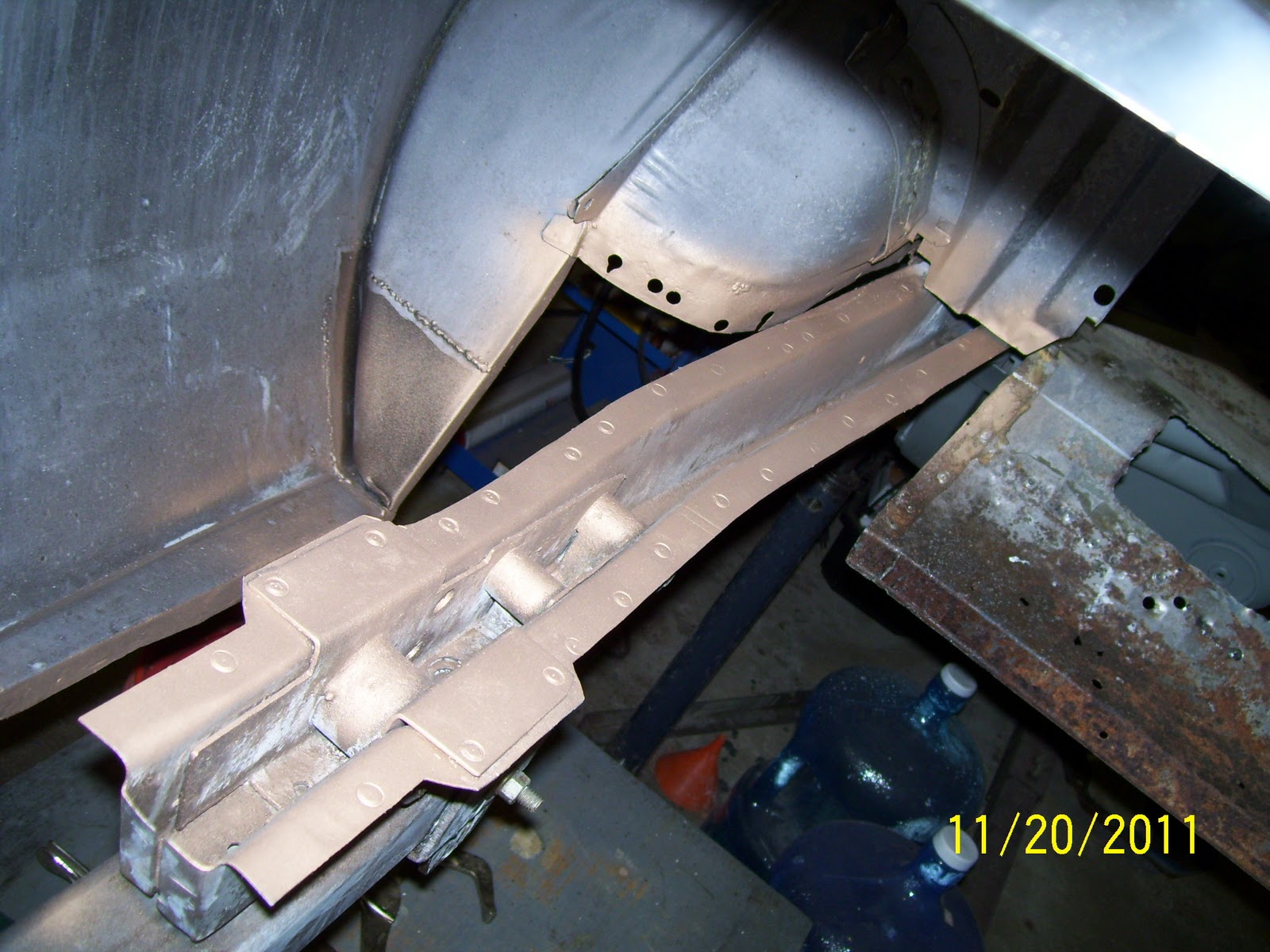
Application of the Esprit product is the same as the Ultra One with either constant spray/cascade or complete immersion.  Since the spray application was the method of choice for me, I used the same equipment I used in my first test to apply the Esprit solution, but I did drop a few pieces into the solution just so I could see how effective the immersion technique would be.  I targeted the inner rear quarter panel of my Boss for this test since the rust in this area was about equivalent to the roof rust I removed with the Ultra One, so I felt I had as close to an apples-to-apples comparison as I could get.

One change I attempted to make was to heat the chelant with a 1500W engine heater plumbed in a constant bypass loop right off the circulation pump.  This would allow me to regulate peak flow at the sprayer by simply diverting any excess flow through the heater circuit and back into the tank, similar to a modern returnless fuel system.  This makes for a much easier job for the pump (no dead-heading) and still allows for simple plumbing to the heater.  The result:  FAIL!  Didn’t work worth snot and proved to be a total waste of time for several reasons.  Most influential was the slow thermal transfer of the heater to the fluid and the rapid heat loss of the fluid to the air as a function of spraying (atomizing) and wetting a rather large, cool surface with a thin layer of fluid.  In short, I need to look at an immersion-type heater to make this work.  Another trip to Tractor Supply…….

Because the scale of the project was considerably smaller than the roof treatment, I was able to use a small cement mixing pan as my containment pan and a fan head garden sprayer for delivery.  Having learned my lesson about fluid loss based on my earlier trials, I elevated the pan on a quartet of plastic 5-gallon buckets to minimize splash and keep everything closer to the work area. 

Satisfied that everything was secure and ready to work, I set the process in motion and adjusted the spray head to provide the maximum coverage possible without spraying expensive chelant all over creation.  After a few short hours, the results were quite impressive.  Rust was definitely being removed but I started to notice a few new characteristics I had not seen with the Ultra One product.  First, all of the plastic, rubber and vinyl parts and some of the painted parts that come into contact with the Esprit chelant develop a glossy, slightly sticky surface. 

Also, over time, the edges of the wetted areas develop a copper-like residue just outside of the grey/black film that develops as part of the process.  I am pretty sure this is a byproduct of the metallic ions leeched off of the brass/bronze valve & hose fittings I use in the plumbing scheme.  No big deal as it scrubs off rather easily with scotch brite pads, but interesting nonetheless.

I am happy to say the Esprit Performance Rust Remover works well.  I admit that it worked a fair bit slower than my June test of the Ultra One product, but this is mostly attributed to the fact that the chelant is forced to operate at about 70°F at this time of year in my shop given that my heating approach failed to function as intended.  A clear lesson I have learned is that rust removal time (a.k.a. chelant effectiveness) is drastically improved with increases in temperature, with my defacto target temperature being about 120°F.  Even though both product suppliers indicate the chelant can be heated to a higher working temp, I think the benefits vs. risks of going any higher than 120°F are such that it makes no practical sense to aspire to a higher temperature target.

So, with the test results from both the Safest Rust Remover and Esprit Performance Rust Remover in hand, what’s the verdict?  Actually, the answer is a bit complicated. 

1.     First and foremost, BOTH products work as advertised.  I remain absolutely convinced that the ONLY way to purchase chelant for any project that will require a volume exceeding ½ gallon is in concentrated form.  As such, this tends to steer a consumer to one of these two suppliers based on my experience and research. 

2.    Unfortunately, the specter of cost forges the point of my biggest complaint between the two suppliers.  The absolute straight skinny on cost is that Ultra One commands a comparative “King’s Ransom” for their gallon of concentrate at $100 US/gallon!  Rust Depot, on the other hand, commands “only” $62.50 US/gallon for what is functionally the same product.  Add the usual shipping premium that most any carrier applies and you are not talking about insignificant differences in cost.  Ouch!

3.    Performance of both products is quite good.  Equivalent for the most part, in fact.  The chelation process doesn’t give a crap at how nasty the rust is that it is being asked to remove.  As long as you keep delivering viable (e.g., non-saturated) chelant to the rusted surface, this stuff keeps eating it until there is absolutely no rust left.  All this without damaging the parent metal.  Think of chelation as “targeted rust removal”.  A “smart bomb” for rust, if you will.  In my experience, the speed of rust removal is directly proportional to temperature and I need to come up with a much better method of heating the chelant.  As development in this area continues, I will document it here.

4.    Both products react rather aggressively to leaded body filler and galvanized metals (particularly zinc I think).  This makes perfect sense as I think about what chelants are designed to do from a medical perspective.  They capture metallic ions in the blood and allow them to be excreted from the body.  Our old Mustangs use genuine lead body filler at the top of the A and C pillars where the roof seams are located.  As such, the chelant eats rather heavily into this material as it goes about removing surrounding rust.  Generally, this isn’t a big deal, but beware the effect this may have on the used chelant solution and how you treat and dispose of it.  Neither supplier had ever heard of or experienced this phenomenon so I was on my own.

5.    Customer service is one of those things that mean different things to different people.  I absolute abhor crappy customer service and I am of the opinion that the advent of the “internet-based” business has allowed the degradation in customer service to accelerate at an unnatural rate.  Fortunately, both suppliers proved somewhat available for questions and both suppliers were very familiar with the hands-on application of their product.  But without being too pointed, I spent less and got more.  I’ll leave it at that.

6.    Clean-up after treatment is one place where I found the two products diverged significantly.  As I mentioned before, the Esprit Performance remover left all non-metallic parts with a slightly sticky, glossy residue and areas where chelant was allowed to run and dry required a bit of scrubbing to get clean.  I did not experience either of these conditions with the Ultra One product and I expect this may be due to base formulation differences, like the addition of the detergents in the Esprit formulation.  For me, I would just as soon see Esprit do away with the detergents and lower the cost even more…..at which point their product would be a double-tough act to follow.

In summary, I am sold on the process.  However, I am convinced there is plenty of room to improve the application of chelation to the automotive restoration process.  Fortunately, I have several ideas I plan to test and report on this blog in the hope that my fellow restoration hobbyists can benefit.  Also, I have found one more chelation product that may just prove to be the silver bullet for most adventurous enthusiasts that want to try the chelation process for rust removal but either can’t or don’t want to invest in the equipment to spray and recover liquid chelant.  Also, I have a request (by a group of individuals, NOT a manufacturer) to review one of the most popular premixed, commercially available chelation solutions as well.  So there’s plenty more to come.
Here is my attempt at heating the chelant.  I used an inverted 1500W engine heater setup in bypass right out of the pump.  Looked nice and clean and worked for CRAP!  I'll have to come up with something else.....
 
Chelant is in the catch basin and the system is ready to go.  Note how clear the fluid is in the beginning.

With the flow regulated by the amount of fluid I allow to bypass through the heater, I set the spray head to cover the rusted area as completely as possible.

I managed to capture the bulk of the overflow quite successfully using this simple concrete mixing pan.  The foaming you see here is a result of the returned fluid agitation as it splashes into the recovery basin.  Within an hour, the chelant starts to take on the distinctive "rusty water" color seen here.


The next series of photos are intended to show the progression of the rust removal process over time.  The total spray time from start to finish is approximately 10 hours.