After MANY weeks of repairs and prep work, I have finally reached the point where I could install my one-piece floor pan. For me, this marks a milestone in the restoration as it will be the first time in a very long time that my car won’t look like the former owner was Fred Flintstone. Most of the snide comments I have endured about how my car looked like a piece of fecal matter were based on the rotten floor and cowl panel. Well ladies and gents……today’s a new day!
With all of my preliminary prep work complete, I was finally able to test fit my new floor and mark all of the obvious areas that would require attention in order to get the floor to fit just right. As I have mentioned many times in the past, there is no such thing as a repair panel that fits out of the box, and this floor was no exception. However, of all of the panels I have installed, this floor was by far the best of the bunch, and considering its size and complexity, surprisingly little work was required to get the fit I was looking for. In fact, the only complaint I have (as do most 69-70 owner’s I’ve talked to) is that the stamping details in the front floor sections are not correct for the 69-70 Mustang. I have struggled with this fact for months and months and have decided to leave well enough alone (for now anyway) and not cut out and replace the offending stamping. I just can’t bring myself to molest a perfect (and expensive) one-piece floor. I’m sure the MCoA purists will damn me to hell for that, but they can pucker up..........
The test fit revealed a number of areas that required slight trimming, bending, stretching, etc. to get the fit correct and I marked these areas with my paint pen for future reference. A lot of the small tweaks were able to be accomplished with gentle bumps with either my rubber mallet or my planishing hammer. After a few hours of massaging, note taking, paint pen indicator placement and picture drawing, I had a pretty comprehensive idea on what I was in for. I finished up the trial fit by tracing around the front and rear sub frames, trans cross member, rear torque boxes, rear trans tunnel, rear floor board transitions, and toe board and firewall flanges so I could accurately locate the spot weld holes I would use to weld the floor in place (all 240 of them!).
Next, I moved on to drilling and/or punching all of the spot weld holes using my body assembly manual as a guide. This took the better part of two evenings to complete, but with the help of a good step drill and a pneumatic punch, the results were quite nice and the drilled holes only required a slight deburring with a chamfering bit to make everything ready to go.
With all of the weld locations prepared, I decided to spray a couple of coats of Zero Rust to the remaining bare areas along the inner rockers and rear sub frames. I masked off the flange areas that I needed to weld to and sprayed two good coats on all of the surfaces and let them dry for a day or two.
After making a number of small adjustments and modifications to the floor that I defined during the initial fitting, I enlisted my dad’s help and we fit the floor in its newly prepared home for the final time. One thing to remember when fitting a full floor pan is that the thing is very springy and stretchy. Because of this, you have to think ahead about how best to install this bugger to make sure the fit on the outermost flanges is proper and that no unwanted gaps are created when you start welding. I find it best to lock down the peaks of the trans tunnel at the front and rear first, and then slowly “float” the floor out toward the sides with strategically placed plug welds at the front sub frames and the corners of the inner rocker panels. With these few points anchored and fitting well, you can minimize the chances of the floor drawing up on you while you work on other areas.
With the floor tacked in, I fashioned a couple of wooden “clamps” to pull the floor flush to the front sub frame flanges so I could keep the fit nice and tight at the flange and make it easy to weld. I simply cut 6” lengths of 2 x4 lumber and drilled a 5/8” hole in the middle of each one. Then I sandwiched the sub frame on top and bottom with the wood and ran an 8” carriage bolt up through the sub frame locator hole and tightened it up snug from the inside. This kept the floor firmly clamped against the sub frame flanges and gave me the nice tight fit I was looking for. After welding the locations directly around the blocks, I was able to safely remove them without loosing that fit.
Before finishing the welds on the front half of the floor, I moved to the area behind the rear torque boxes. This is probably the most difficult area to get to fit well and is most prone to crawling around during install. As such, I decided to lock this area down first and then move on to the front. Here again, strategically placed anchoring welds made fitting much easier, but careful use of Clecos helped guarantee the fit on each side.
Once I had the rear floor “wings” fully welded, I moved back to the front and started welding along the trans cross member flanges from the top down, using Clecos to help pull the floor to the form of the cross member as tightly as possible. As I worked my way down each side, the fit against the front toe boards began to get better and better until all that remained was to simply weld them in with almost no manipulation or clamping.
With the front part of the floor essentially done, I moved back to the rear transition panel flanges. I wasn’t quite happy with the fit in the inner corner of the patch I made, so I decided to modify it slightly to match the form of the new floor, now that I had a nice panel reference to work from. So out came the screaming wheel of death (a.k.a. pneumatic cutoff tool) and a clean slice down the offending corner was taken. This allowed me to begin forming the panel to match the contour of the new floor, starting with the bottom and working up. I used Clecos to hold the shape I wanted and then formed the top half down to match. When I had both pieces match to the contour, I trimmed them both again to match each other and welded the corner back together. The fit was exceptional and will look fantastic after a bit of metal finishing. I finished up the rear floor area by welding in the lower rear seat flanges and outer wheel house flanges then moved on to the inner rockers and completion.
The inner rockers were the last areas that required welding and this was another example where a rotisserie is invaluable. I rolled the car on its sides to complete the welds along the inner rocker flanges while maintaining a relatively comfortable working position. About 50 spot welds later, and my new one-piece floor was in!
Next on the agenda is a lot of spot weld grinding and some relatively simple metal finishing work under the car before installing the seat pans. It’s kinda surreal to see my old car with a pristine and complete floor in place!
 |
| The first fit on a major panel is always an exciting one. I was pleasantly surprised to find the new one-piece floor fit remarkably well, requiring only minor massaging to get the fit just right. |
 |
| Using a few simple tools (including a digital camera), the entire floor panel was evaluated and adjustments made to get the fit as close as possible and/or mark areas that required further work. |
 |
| Here you can see a slight gap to the passenger side outer flange caused by the "under-bent" flange that mates to the inner wheel house. I mark these areas with a white paint pen to show what needs to be done to avoid confusion when the panel is out of the car. |
 |
| The same condition existed on the driver side and a similar modification was required to allow the gap to close. |
 |
| It is important to get the fit at the for corners of the main floor section nice and tight so they can be welded early in the process to act as structural "anchors". This makes getting the rest of the floor to fit properly much more agreeable work. |
 |
| With the floor fit established, I trace around the interior flanges with a white paint pen to help in locating the required spot weld holes. Here I have traced the passenger rear torque box area just above the front spring mount with paint pen. |
 |
| Here is what the panel looks like out of the car with the flange areas clearly visible. |
 |
| Another example of how nicely the paint pen traces show where the edges of flanges are located. This saved a lot of time when laying out spot welds for panel replacement. |
 |
| After all of the spot welds are located, drilled and deburred, what is left is a panel ready to weld in with no fuss and all of the holes where they need to be. All of the holes along outer flanges are punched using a pneumatic 5/16" punch tool and all interior holes are drilled to 5/16' with an inexpensive step drill. |
 |
| Another view of how nicely the paint pen traces help in locating spot weld holes on interior flanges. These holes are located on the passenger front subframe rail. |
 |
| A pneumatic punch is unbelievably efficient at making beautiful, distortion-free weld holes along any outside flange. Your restoration life is not complete without one of these tools! |
 |
| All spot weld holes have been drilled/punched and the floor is now ready to install. |
 |
| One last step is to coat the remaining phosphatized areas with a couple of coats of Zero Rust paint. I taped off the weld flanges before painting, but in hindsight, I will not do this again. I prefer the added protection of having this paint everywhere I can and cleaning each weld hole is easy enough with a 5/16" drill bit ground flat on the end. Even though it makes for a more smoky environment and a bit more sputtering when you light up the weld, I like the idea that there is something between these flanges. |
 |
| Left rear torque box area after Zero Rust. |
 |
| .....and the right rear...........ready to go! |
 |
| I sprayed each inner rocker at the same time, but this time I did not mask off the weld flange area. |
 |
| I prefer to anchor the four corners of the main floor and then the peaks of the front and rear trans tunnel area. This allows me to "float" the remainder of the floor over the structural contours for the best fit possible. |
 |
| I fashioned these simple clamping blocks to allow the floor pan to be pulled up tight against the front subframes to ensure good tight flanges along the full length. I added welds before and after the blocks to lock everything down and then removed the blocks to finish the job. |
 |
| Here the blocks have been removed and you can see the anchoring welds to either side. With the forward floor section tacked in and secured, I moved to the rear to get it fit properly and secured in similar fashion. |
 |
| In similar fashion to the front, a series of strategically placed welds along the rear subframe sections and along the edges of the torque box allowed me to float the rear floor wings out such that the outer flanges fit almost perfectly. |
 |
| The same technique was used on the driver side with equal effectiveness. |
 |
| Shifting back to the front, I started working my way down each side of the trans crossmember ensuring the fit was nice and tight at every weld location. |
 |
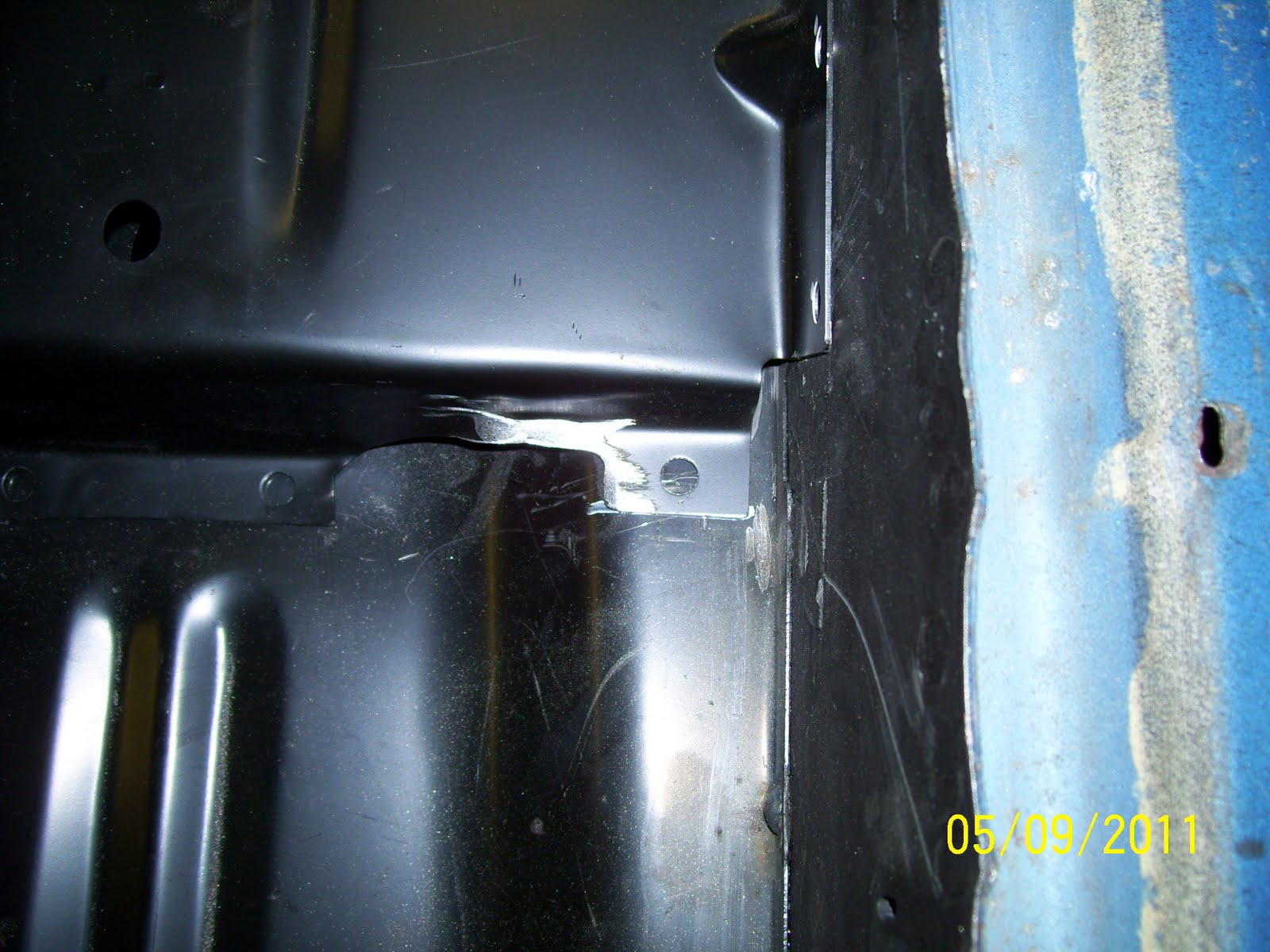
| This technique resulted in a fit at the bottom interface to the subframe that was actually better than the original floor. |
 |
| At the front of the crossmember, the fit was equally good and the interface between the firewall/tunnel and toe boards was very good also. After completing the welds along the subframe flanges, the front of the floor was essentially complete. Back to the rear! |
 |
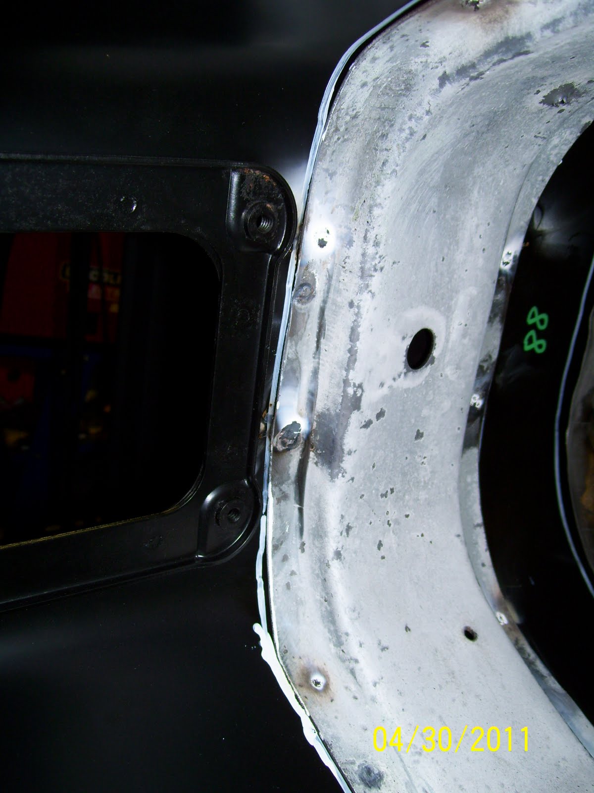
| I wasn't entirely happy with the fit of the interior corner of the transition panel patch I made earlier. Though it wasn't horrible given I had nothing to reference against, I wanted it to be better. So I sliced the corner through with my abrasive wheel and started working the metal to conform to the contour I required. |
 |
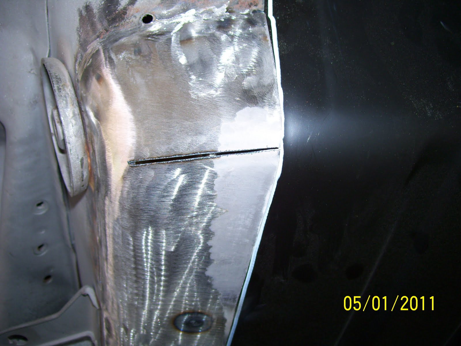
| Though the picture seems to exaggerate the mis-match to a greater proportion, it does give you the idea of what needed to happen. In this picture, the left edge will be formed first. |
 |
| Forming the corner creates an overlap of material. The clecos help keep the form in place such that the abrasive wheel can be used to trim the overlapping material and allow the corner to be welded solid again. |
 |
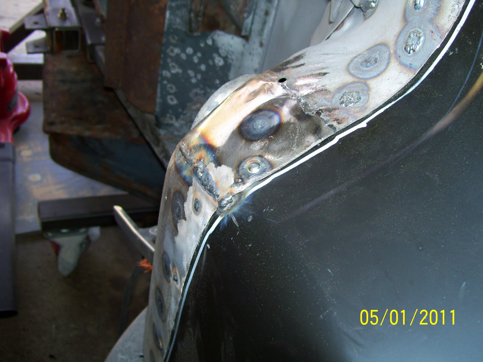
| Here you can see the reformed corner ready for welding. The fit against the floor contour is excellent and will require very little metal finishing once welding is complete. |
 |
| Welding of the corner is now complete and ready for grinding and metal finishing. I am much happier with this fit than before. |
 |
| With attention returning to the inner rockers, I completed the installation by welding all of the remaining locations along the length of the rocker. |
 |
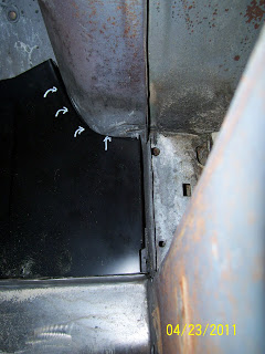
| The rear view of the finished floor installation. It's kinda hard to imagine how poorly this same area looked last fall when the miserable remains of the original floor were still intact. |
 |
| The final floor installation looks quite nice! The seat risers are now being mocked-up for fit and installation along with hours of weld grinding and some simple metal finishing. |