Thursday, June 20, 2013

13” Front Disc Brake Installation: The Right Stuff ...... Detailing that is!

Another solid week of work yields another completed phase of the front suspension and braking system assembly.  This week, we tackled the job of assembling the entire 13” front disc brake system on the freshened drum brake front spindles and hubs and the results were exceptional.  I love working with well-engineered, solid parts that require no fiddling to make fit and/or function.  Luckily, we’re batting a thousand lately!

To begin the latest adventure, we started by cleaning up the drum brake spindles and hubs in preparation for powder coating.  As many Mustang enthusiasts have often painfully discovered, the production Mustang spindles are very roughly machined forgings with lots of raw, sharp edges that are just begging to mutilate human tissue.  At the same time, they don’t look particularly sanitary and as such, became the focus of considerable smoothing with the angle grinder and some 60-grit discs before heading off to the blast cabinet.  After a few minutes of abrasive clean-up, the spindles looked amazing and were set aside for later cleaning before powder.
On the hubs, it was necessary to turn the O.D. of the flanges down a bit in order to properly fit the re-drilled, 13” vented (Brand X) rotors.  As an aside, these rotors have a 0.480” more inboard offset in the hat area over the “Cobra” 13” rotors to allow fitment of a wider selection of wheels without the need to use wheel spacers.  By simply re-drilling the rotors to fit the Ford 5 x 4.5” bolt circle, these rotors are a simple bolt-on choice with a wide variety of feature options in the aftermarket.  We will ultimately upgrade the front rotors at a later date, but all smoke-testing will be done on the standard rotors as shown here.

Once the hub O.D. machining was complete, they received the same abrasive clean-up as the spindles and both pairs of parts were prepped and powder coated in our standard urethane satin black that we use for all of the under-car components.  Once out of the oven, the hubs and spindles looked virtually flawless and we now had a clean foundation to begin the build-up of the assembly.
Assembly of the hubs was begun first by pressing in a full complement of new wheel studs, followed by new bearing races.  Then, each hub and spindle was test fit to seat the bearings as well as verify the fit of the new spindle nut/washer & retention cage before show time.  With the hub and spindle fit verified, we moved on to the fitting of the caliper mounting brackets.

As you may have noted, the spindles and hubs we are using are from a drum brake version of the Mustang and not the original disc brake parts that were originally equipped on the 1970 Boss 302.  There are a few reasons for this that are actually quite simple:  First, the drum brake spindles have a 4-bolt pattern that retains the brake backing plates whereas the disc brake spindles use only three.  The 4-bolt flange makes for a much more stable mounting configuration for the disc brake brackets.  Secondly, the disc brake spindles have a large mounting hole in the spindle upright and an awkward hole/flange grafted onto the steering arm section that are used to mount the production disc brake caliper bracket.  With modern 13” brakes, these holes are not used with this brake combination and historically, these areas of the spindle have proven to be weak points in this design in heavy duty and racing applications.  Besides, disc brake spindles are ugly………so there.
While Street or Track apparently no longer offers the “Cobra” front caliper mounting brackets we use here, they are relatively simple, very high quality devices that install on the 4-bolt backing plate flanges and include the aluminum adapter to properly locate and anchor the production caliper bracket.  In our case, the left and right hand side adapters had to be spaced inboard by .060” on each pad to account for the differences in the production tolerance stack-up to center the caliper brackets over the rotors.  With these details covered, the adapter brackets were torqued to final spec and we were finally able to shift our attention to the final assembly of the hubs.

Since both hubs were already mocked up on the spindles, the assembly process was very simply a matter of cleaning and greasing the wheel bearing cones with bearing grease, installing the wheel seals and sliding them into place on the spindles.  The spindle nuts were installed per the factory shop manual specifications and secured with new retention cages and split keys. 
Now for the REAL excitement!  Our friends at The Right Stuff Detailing (TRSD) have been in the disc brake conversion kit business for a long time and supplied their beautiful, dual piston “Signature Series” PBR calipers in smooth, glass black powder coat finish. 


If you have never heard of The Right Stuff Detailing, take notes.  This is a fantastic company with outstanding products and customer support and their specialty is braking system conversions and components along with custom and pre-bent tubing products, and custom and pre-made e-brake cables and a host of other braking and suspension offerings.

These calipers are a smoother, cleaner version of the classic Cobra/Corvette calipers that have been so popular in the world of classic Mustang disc brake conversions, WITHOUT the gaudy casting “identifiers” tacked all over them or the need to rebuild salvage-yard cores.  Their Signature series calipers are produced to the same exacting OE level specifications as the production model calipers and can be serviced in exactly the same way and with exactly the same parts as the production versions that are now essentially unavailable.
Here again, I am very happy to report that these calipers and brackets bolted on to the spindle assembly with absolutely no drama whatsoever after installation of a fresh set of semi-metallic brake pads.  After all, with OEM-level quality on all the TRSD parts, and standard brake hardware, these calipers don’t know they are, in any way, a part of a custom brake application.

With the TRSD calipers and 13” front rotors solidly in place, we took a step back to admire the beautiful simplicity of the setup.  Almost “elegant’ I would say.  Of course, the visual aspect is enhanced by the sheer size of the rotors and the capability that comes with them.  The Night Mission Boss 302 will STOP with authority to be sure.
As a final measure, the installation of the spindle dust caps presented the next dilemma, and one I had anticipated based on past experience:  Fitting new dust caps WITHOUT beating the snot out of them and/or damaging them during installation such that they look terrible on close inspection.  I absolutely HATE the look of dinged up dust caps on custom cars and would not settle for anything but a clean installation on this project.  I know, I know…..nobody will ever see them, but that is entirely beside the point.  If I know they look terrible, it will eat me alive until I fix it.  So……needing little prodding to dust off my lathe for a project, Ted and I set about making a proper installation tool that would allow the dust caps to be installed in the hubs with minimal effort and absolutely no damage.

Since I already had a nice driver handle that was included in my bearing and seal driver kit, I figured I would make a dust cap driver that would fit that handle for ease of use.  So after a few measurements and a quick design sketch, I scoured the scrap aluminum bin in the shop and popped up with a perfect chunk of extruded 6061 aluminum rod that would work perfectly and require relatively little work to create the tool I needed.
With the South Bend 9” lathe well lubricated and warmed up (ya have to do that on 77-year-old machines), I proceeded to whittle out a driver cup that fit my drive handle perfectly and allowed the dust caps to be driven easily into the hubs with not so much as a scratch on any component.  In fact, the simple tool worked even better than expected and relieved me of the burden of worrying about how my hidden-from-human-eyes dust caps looked.  Another thousand-dollar solution to a ten-cent problem brought to you by your buddies at the Night Mission Boss 302 project!

Anyway, there you have it:  A complete and very capable “big-brake” conversion on the Boss is now in the books.  Soon, we will once again shift back to more “bodywork” type work as we set about spraying the exterior floor pan with Raptor bed liner while the weather is being so cooperative.  Thrown in there will also be a round or two of powder coating front and rear suspension components before we dive back into the engine bay for a host of filling and smoothing operations as we head into the late summer/early fall season.  In between all of that, I have plans to do the Street Rodder Tour from San Antonio, TX to Pigeon Forge, Tennessee with in early September and I am completely fired up about spending a solid week doing nothing but cruising God’s Country in a ’32 Coupe with my uncle.  Truth being what it is, I continue to learn a lot about “smelling the roses” every day.  Until next time!

Close inspection of the stock Mustang spindle will reveal a large number of rough, sharp edges that need smoothing.  We knocked these edges off and spent a good bit of time smoothing all of the other surfaces to make for a nice presentation once in powder coat.
 
After turning down the O.D. of the stock hubs and smoothing and powder coating them, new wheel studs were pressed in.
 
With the new bearing races installed, the hubs were test fit on the spindles to seat the races and make sure there were no surprises in their operation or fit.  You can also just make out the smooth surfaces of the powder coated spindle upright.
 
Here, the Street or Track caliper adapter brackets are test fit to the spindle.

The hubs are re-installed to test fit the entire brake system componentry.  Note the hub-centric adapter ring that is now positioned over the center of the hub to locate the rotor properly.

Test fitting the components showed that we needed to install 0.060" shims (see yellow arrow) to account for tolerance stack such that the caliper mounts would center over the rotors properly.

With all adjustments made and fit of all components verified, the adapter brackets were installed permanently with all fasteners torqued to spec with red Loctite where applicable.

Final assembly of the hubs included moly-fortified wheel bearing grease packed into new Timken bearings and buttoned up with new seals.
 
The 13" rotors are an impressive sight bolted to the hubs.  Plenty of braking capability in this package to be sure!

And here is the feature part!  These beautiful Signature series PBR calipers and brackets from The Right Stuff Detailing are as good as they come.  Absolute top quality and OE-level quality and reliability make these calipers extremely hard to beat.  Couple that with a clean, elegant look that is anything but gaudy, and the combination is just about perfect!

Dust cap installation can be a challenge and I particularly hate beat up dust caps on custom cars.  I decided to design and machine a dedicated driver tool that would allow the dust caps to be driven into the hubs squarely with no hint of damage.

The tool is designed to use my bearing driver handle and it worked perfect in driving the dust caps into the hubs perfectly square and undamaged.  Here, the dust cap has already been driven in .

Simple in concept, the driver simply cover the cap and drives it home using the cap flange.

A thing of simple beauty that nobody will likely ever see.  A perfectly undamaged dust cap.  As I said above, a thousand dollar solution to a ten cent problem........I'm sick.

Here are the TRSD calipers and 13" brake rotors in place in all their glory!  I absolutely love the elegant simplicity and absolute purpose this entire assembly displays.  Once all of the bare steel parts are finished in black powder coat, this will be an amazing complement to the project. 

Tuesday, June 11, 2013

Unisteer Rack & Pinion Test Installation!

Mechanical work continues on the Night Mission Boss 302, and in this round we complete the installation of the Unisteer steering rack.  But first, some history:
Rewinding back to August 4, 2011, a quick mock-up showed we had a lot of work to do to get the Unisteer rack & pinion steering rack to fit the chassis.  A lot more, in fact, than what is indicated in the installation manual.  Fortunately, I have had a considerable amount of time to think about the best approach to this installation along with a few tweaks that I felt were required to make the installation cleaner and for functionality of other systems and adjustments to remain as unaffected as possible.  Things like oil pan clearance, accessibility to lower control arm camber adjustment bolts and cleaner overall appearance were all things I pondered heavily before arriving at some pretty simple modifications to the bracket that solved all of these issues in the least intrusive manner possible.  In fact, I was so happy with the modifications that I plan to pass them along to Unisteer, along with my steering column modifications, in hopes they find the information useful in helping to evolve the product and improve the downstream customer experience for those that decide to make this conversion in the future.  Here’s hoping!
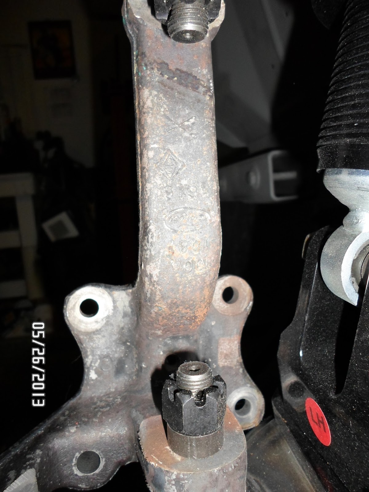
The first order of business was to identify the areas of the chassis that would need to be modified to allow the rack mount to fit properly and to get a good picture of what would be necessary to improve camber bolt adjustment access. This was made considerably easier by removing the rack from the mount and working with the bare mount for all fitting and clearance checks.
First, we marked the rear lower control arm pocket flanges with a marker to show exactly how much material would need to be removed for proper rack mount fit.  This ended up not being as extensive as I had originally estimated and was accomplished rather quickly with the pneumatic cutoff wheel.  After about a half hour of work per side, the rack mount fit snugly into place with little fanfare and the focus could shift to the camber bolt access.  This was a truly welcome relief as I had anticipated a much larger tear-up based on my original assessment.
Camber bolt access was an area that, in fact, required more modification than I had originally envisioned.  The position of the holes provided by Unisteer was too far inboard to allow proper access of tools and range of adjustment.  Fortunately, the hole size was sufficient and I determined a simple elongation of these access holes would give me everything I needed to avoid having to remove the rack assembly when camber adjustment at the lower control arm was required.  So, turning to my trusty paint pen, I roughly sketched out what the new oval access hole needed to look like so I could come back a bit later and formalize the shape when it came time.
Next, the rack mount was removed and the rack assembly installed on it to allow the entire system to be bolted into place to make final evaluations of some aesthetic features and clearance concerns.  The first concern was the driver side lower control arm operates with tight clearances to the end of the rack mount and I didn’t care for the overhang of the flange in relation to the aluminum rack mounting block.  So, I decided to kill two birds with one stone by marking the left vertical edge of the mount to match the rack mount block and thereby add a bit of clearance to the lower control arm.  This would also make the left side match the finish on the right side where the design already was made to nicely match the rack mount block.  Of course, this is a detail that nobody will likely ever see or recognize, but it matters to me that it gets addressed and it made “right.”  At least in my book anyway.
Secondly, there is a strange and unnecessary lump of steel on the passenger side of the mount that serves no purpose other than to restrict starter and header clearance and potentially conflict with certain oil pan designs.  For me, there was the added aspect of symmetry that I try very hard to achieve and/or maintain and this bit could not be left alone (imagine that!).
On the driver side, the rack mount makes a nice gentle curve from the chassis mounting flange, across the engine bay to the lower cross brace section.  While maintaining good looks, this also provides for maximum allowable space to fit headers, power steering hoses, wiring, etc.  However, on the passenger side, the same area of the brace is an awkward, angular appendage that constricts this area for no apparent reason and complicates fitting headers, starter and some oil pans.  Besides all of that, it looks funky and I don’t like it (there’s that symmetry thing again).  The solution was to mark a nice, gentle curve that mimicked the driver side and opened up the area for more component clearance while still maintaining good aesthetics. 
Then, off to the band saw to remove the offending material from both the left side rack mount area and the right side cross brace edge.  Once the cuts were completed, a few minutes with the angle grinder had the shapes much more pleasing and functional.
The final modification that remained was to formalize the size and shape of the camber bolt access holes and cut them out and finish them to shape.  Since the mounting bracket is made of hefty steel plate, I decided to rough out the holes with my oxy/acetylene cutting torch and finish them up with the air grinder and hand files.  The end result were two nicely shaped oval holes that allow full tool access and camber adjustment without the need to remove the rack from the car.  An added bonus was that I discovered the camber adjustment plates can be slipped into place in their rear locations without any drama at all!  Bonus!
Finally, I reassembled the rack assembly to the mount and put everything back into the car for mock-up of the tie rod ends and spindles.  Unisteer supplies two different outer tie rod ends to cover all applications of the Mustang spindles and they are distinguished by either large or small taper ball joint ends with either 7/16” or 1/2” retention nuts.  In the case of the 70 Mustang drum brake spindles I am using, the “large taper” ball joints were a perfect fit. 
One interesting, but minor irregularity was that the rack was marked as centered on the steering shaft but was not centered as it was intended when the paint marks were aligned.  So Ted and I did a quick centering exercise and re-marked the rack for center.  At the same time, we discovered the rack was a snappy 2.6 turns lock-to-lock, so the response from this rack should be very nice when everything is finally locked and loaded.
At this point, I am quite happy with where we are on the rack and pinion fitting and soon we will move to mocking up the modified steering column that was completed quite some time ago.  In the meantime, the next phase of the front suspension mock-up will be to fit the 13” vented front brakes on rebuilt and modified production hubs.  Plenty more to come!

Here is the complete Unisteer rack and pinion assembly included in the kit.  The GM J-Car rack is obviously very compact and tidy compared to the factory Mustang steering system in '70.

The areas that will require trimming are marked with a permanent marker.  In contrast to my first evaluation, there was not as much modification required as I originally estimated.  These small modifications allowed the rack bracket to bolt up as intended.
Although the suspension is far from properly adjusted, you can see how tight the clearance of the left side rack bracket was to the lower control arm.  This will need some attention.

With the rack removed and the bare rack bracket bolted in place, the position and size of the camber bolt adjustment holes can be easily evaluated.  As you can see, the holes are fine on diameter, but need to be elongated a bit to allow maximum adjustability and tool access.

The right side camber bolt access hole will require an identical modification.

Using my trusty paint pen, I roughed out the size of the new opening .

This is a better look at the amount of material I would need to remove to get the required access to the camber adjustment bolts.  The angle of this shot makes the bolt head look terribly off center, but this is just a trick of the lens.


A test-fit of the rack assembly shows the bracket fits the frame nicely and the rack clears the structures with plenty of room.  In this shot you can clearly see the camber bolt hole marks I made to show how the hole would be elongated.

The right side rack assembly fits quite well and clearance here is very adequate.
 
With the rack installed you can see how close the protruding edge of the rack mount bracket gets to the lower control arm.  Besides this, this extra material looks a bit untidy, so the only thing to do will be to trim it up flush while gaining a small bit of clearance at the same time.

And there you have it.  The bracket is now trimmed neatly to the edge of the aluminum rack mounting block and we gained about 1/4" of clearance to the lower control arm.  Not a lot, but it should provide a small clearance margin where before there was virtually none.


Looking at the rack assembly from the front, notice the bracket shape on the left as compared to the right.  The material above the black line drawn on the left bracket edge shows the extra material than is unnecessary, gets in the way of starters, oil pans and potentially headers and disrupts the symmetrical "look" of the part.

A closer look shows the cut line more clearly.

With the bracket edge trimmed and smoothed, the mount takes on a nice, symmetrical shape that is more functional and pleasing to the eye.  Yet another detail that 99% of the people will never pick up on, but make a difference (if only to me).

Here is another look at the cleaned up edge of the bracket from the front.

After rough-cutting the camber adjustment holes with the oxy/acetylene cutting torch, we ground the edges smooth and snuck-up on the final shape with some careful filing.  You can see how much more access this modification provides and how much easier it will be to get tools in there to tighten the fastener and/or change the camber adjustment plate.

The right side camber adjustment bolt opening is also very accessible, even with the rack installed.  We can work with that!