Saturday, September 19, 2015

Hard lines, Pedals, Bulkhead Terminals & a Few Other Tips!

Behind, behind, behind!  That has been just about the story of life around here for the past month.  We 40 tons of concrete in the ground BUT we need 40 MORE tons to go before we can start construction.  And every day we wait is a day we waste!  GRRRRR!

This update is basically an account of what has kept me sane over the last month to avoid committing a felony while waiting on concrete contractors.  Car building is therapy to me and that has never been more obvious than in the past few weeks!  The good news is I have been able to get a lot of little things done and collect up a few tips to share along the way.  So let’s get to it!
As many followers of this build blog will recall, there is absolutely nothing in the suspension and braking systems of this car that remain stock.  Far from it in fact, and with that, the brake system hard line plumbing is a fully custom job from front to back.  This is not only driven by simple necessity, but also the fact that I am very particular about brake line visibility, especially in the engine bay.  The bottom line is, I HATE seeing brake lines in the engine bay and Mustangs are notorious for a lot of “in-your-face” brake line plumbing in factory form.  Well…….not this one.
While I did a poor job of photographing all of the intricate details of the new brake hard lines, I did capture some of the more sanitary aspects as well as a few trick bits I use on custom builds that are worth sharing.

The first “tip” I wanted to share was a little known product called “Quick Clips” from TJ Tool out of Rogers, AR.  These nifty (and patented) little hard line clips are just about the most discrete and cost effective means of attaching hard lines ever invented and they cover the widest range of sizes of any I have ever found (from 3/16” to ½”).  As the story goes, Quick Clips were designed by Kenny Davis Hot Rods and shared with the likes of Troy Trepanier (Rad Rides by Troy) and Chip Foose on a few of their spectacular builds and the rest, as they say, is history.  Soon, Quick Clips were being manufactured in bulk and made available to us mere mortals at an absolutely excellent price.  Each clip is located using a 9/32” drilled hole and is simply pushed into the hole and retained with a heavy duty “Christmas tree” barb. Once it’s in place, you simply snap in your line and move on to the next one.  It couldn’t be simpler.

Next up, I often find the need to pass brake lines through frame sections in order to keep the presentation tidy and tightly tucked to the parent surface.  For this job, I like to use stainless steel thru-frame fittings from Stainless Steel Brakes Corp (SSBC) for a couple of key reasons.  First, they offer a size range that works perfectly with a lot of the frame sections I deal with.  Second, they use standard 1/8” NPT female ends that allow maximum fitting configuration flexibility and the ability to keep any associated plumbing a tightly tucked as possible.  And finally, they look great!

On the Boss, I use the SSBC thru-frame fittings to discretely route the lines from the master cylinder to the outboard side of the driver frame rail and again on the passenger side to route the right front caliper line outboard as well.  Since this car is fitted with rack and pinion steering, I simply enlarge the appropriate steering box and idler arm mounting holes to fit the thru-frame fitting O.D. (they just BARELY fit!), and run them through.  Simple and clean.  I like that!

Another Mustang-specific upgrade that is worth one of those “holy sh*t” remarks when completed is a ball bearing clutch pivot conversion.  Now, for the record, there are a number of bearing conversions on the market that are intended to upgrade the Mustang clutch pivot shafts/bushings.  However, most of these are absolute junk or they are not properly engineered for long-term use and reliability.  In simplest terms, if the conversion EVER involves running roller bearing needles directly on the clutch shaft, avoid this design at all costs!  The clutch shaft is not of the proper material or hardness to endure long term use as a bearing race under any circumstances.  In addition, these inferior kits rely on an almost perfect clutch pivot shaft to work or a new shaft will be required, at which point you have to start asking if the repair is likely to be cost effective and reliable over the long haul.

Having said that, there is one solution offered that frankly is head and shoulders above the rest in quality, dependability and repair-ability and that is the conversion kit offered by Steve Wilkes at MustangSteve’s .  The MustangSteve’s ball bearing clutch pedal conversion will require more installation effort as a whole than any other kit out there, but the end result is far and away superior to anything out there and can be used successfully with shafts exhibiting rather heavy wear based on the fact that the ball bearing inner races operate on the outer ends of the pivot shaft and away from the normal wear surfaces that plague the stock pedal pivots to begin with.

The quick and simplified overview of the install involves removing the remains of the original (and likely thrashed) pot metal pivot bushings and welding a pair of spacers to the inner shaft pivot holes in the pedal bracket and following that up with welding on the bearing housings to the outer pedal bracket.  Once the welding is completed, the bearings are simple slide-on operations over the pivot shaft and are retained by the stock Mustang retention hardware.  The end result is an unbelievably smooth clutch pedal operation with far less effort than even the best the factory Mustang mechanism could offer.  This kit is truly one of the best $40 investments you might ever make.

Finally, another modification in support of under hood cleanliness!  Like brake lines, I absolutely loathe the look of batteries no matter where they are.  Hate ‘em.  I don’t care if they are in the trunk, under the chassis or wherever; if I can see it, I hate it.  And, in similar fashion to brake lines, I don’t like the look of battery cables under the hood and I do everything I can to keep them as minimal and out of sight as possible.

To help in this, I like keeping battery cables tucked inside the car until absolutely necessary and then passing them through bulkheads and/or firewalls using a quality terminal bulkhead connector.  There are a number of different styles out there, but the two designs I prefer are the round thru-panel design that are retained by a large jam nut or the bolted design offered by Painless Performance. 
On the Boss project, we opted for the round, thru-panel design for their simplicity and overall better looks.  I find those offered by Jeg’s are of very good quality and are available in both red and black for polarity separation.  These terminals require a 1 ¼” hole to be cut into the panel to fit.  With a thin film of urethane body sealant or silicone gasket maker, these terminals are weather tight and look very clean.  Plus, with a bit of ingenuity, you can trim a pair of alternator charging terminal boots or battery terminal covers to insulate the connections once they are made up for an added measure of protection and cleanliness.


Well, that’s about all for the moment.  Fortunately, these little bits of progress are working well to keep me from killing incessantly unreliable concrete contractors that have conspired to delay our shop project over a month.  I know the work will eventually get done, but until we have a floor, we can’t build squat.  Looks like it’s going to be a busy fall!

Quick Clips from TJ Tool in Rogers, AR are probably the smallest, most effective and easily installed hard line clips anywhere.  I love these things and they work incredibly well!  Cheap too!

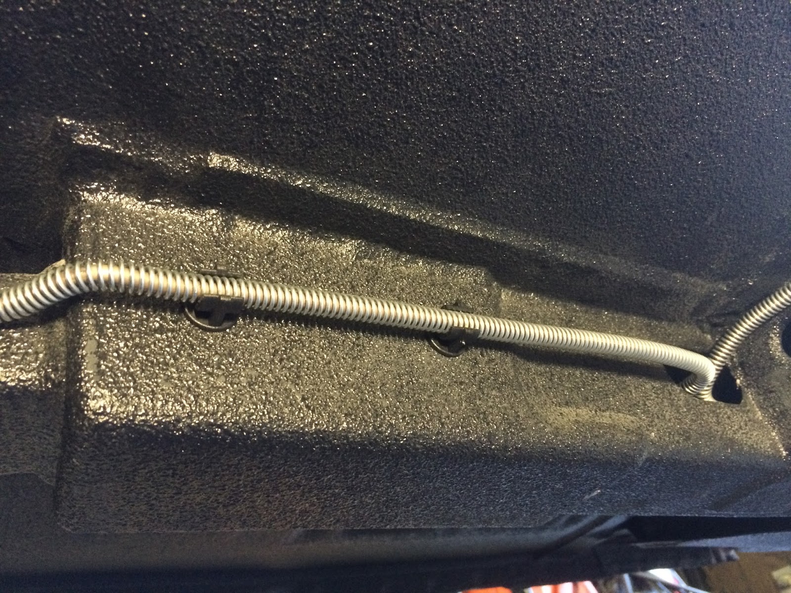
A simple 9/32" drilled hole is all that is required to install Quick Clips and the hard line just snaps into them.  Here is a section of 3/16" brake line with a line armor covering retained at the back of the driver side subframe rail.  I use 5/16" Quick Clips to retain this line and the look is very clean and tidy and the line is very secure.

I have been asked a lot about these thru-frame connectors from SSBC lately, so I thought I'd show what I use here.  This is an example of the 3" SSBC thru-frame connector I like to use.  Very clean and tidy and keeps hard lines tucked tightly against the frame for maximum clearance and a tidy appearance.  The far end of the fitting in this picture is the "nut" end which mirrors the fixed end in appearance when fully pulled up tight.

I hate seeing brake lines strung all over the engine bay so I kept the lines in the Boss project as minimal as possible.  At the bottom, you can see how we routed the lines from the master cylinder to the SSBC stainless thru-frame fittings located where the original steering box mounting holes were.  Since this car has been fitted with a power rack and pinion steering system, these holes were available to be re-purposed!

Again, in the interest of keeping brake lines on the minimalist side, the prop valve is mounted close to the booster and the lines are kept short and cleanly routed.  Look closely at this shot:  Can you find the rear brake line from the prop valve?

Here is the scene from the outside of the driver side frame rail.  In another act of re-purposing available features, the right side front and rear brake hard lines pass from the thru-frame fittings through the driver torque box where the original fuel line originally passed.  These are very tricky bends and there is only just enough space to exit the back of the torque box with both lines.

I modified the original brake hose brackets to work with the -3 AN brake line anchors we needed.  This combination bolts to the factory line bracket locations and allowed a very clean hard line routing to the fitting.  Since the brake caliper combination we have chosen is a "trailing" caliper design (e.g., located on the back side of the spindle), the flexible brake hose needs to be oriented toward the back of the car to allow maximum operational clearance with minimum length.

Using an identical SSBC thru-frame fitting on the right side, the brake line and bracket combination is a mirror image of the left.  The brake hose brackets will be powder coated satin black to blend in beautifully with the under body finish.

This is all the brake line visible in the engine bay on the passenger side.  With the engine in place, this line will be virtually invisible and easily shielded if necessary.

Like untold thousands of classic Mustangs on the planet, the Boss clutch pedal pivot bushings were shot.  While there are a number of different repair choices out there, it was decided that a "lifetime" repair was the only way to go!  This is where a brilliant, ball bearing repair kit from MustangSteve's fits the bill.

Using a small chisel to break the retention tabs off of the original heavily worn bushings, I was able to remove the bushings intact with absolutely no damage to the original pedal bracket.

Here is our starting point:  A clean bushing hole that needs a quick pass in the blast cabinet to clean up before the installation of the Mustang Steve's ball bearing clutch pedal conversion kit.

Skipping a few steps ahead, here is the MustangSteve's bearing holder and spacer washer TIG-brazed in place.  One more on the opposite side and we can fit the bearings and pedal back into place!

A perfect fit and a perfect, lifetime repair to a notoriously lackluster feature of a classic Mustang clutch.  The difference in pedal swing accuracy and smoothness is phenomenal!

From the opposite side, you can see how nicely the kit fits the clutch pivot space and once powder coated black, it will be virtually unrecognizable as anything but stock.

Like the sentiment I have for brake lines in the engine bay, I hate batteries and battery cables in the engine bay as well!  These battery cable bulkhead connectors allow me to route battery cables low and out of sight near the passenger frame rail.  One cable to the starter and one to the block and that's it!

Wednesday, August 12, 2015

Raptor Liner: Fuel Tank & Rear Valence Treatment

In between new shop general contracting duties, I managed to sneak in a few hours of work on the Boss project this week.  I have been working on a few details at the rear of the car and the time finally came to finish the bottom surfaces of the fuel tank and rear valence to match the rest of the lower surfaces of the car.

Some followers of this blog may recall that I am a HUGE fan of U-Pol Raptor bed liner and protective coating material to finish the underside of my project cars.  This incredibly durable, waterproof, semi-flexible and easy to apply sprayable coating is an awesome choice for a very clean, custom appearance on the bottom of the car and it is very easy to maintain and keep looking fresh for years to come.  Truth is:  There is practically no limit to the applications you can dream up for the stuff, but in this case, we keep it pretty simple.
 
A few months back, I prepped and primed the bottom of the stainless fuel tank in preparation for the Raptor liner application.  Since then, I have been working on the fit and finish of the rear valence and with that work now complete and the entire valence primed in PPG epoxy, the time had come to finish the bottom exposed surfaces of each part in Raptor.

Like just about any paint prep, Raptor requires a moderate “tooth” on the surface to ensure optimum adhesion of the product.  To achieve this, I scuffed all of the surfaces with a red Scotch Brite pad and wiped everything down with prep solvent to ensure the surfaces were absolutely clean.  Then, a few run downs with a fresh tack cloth and it was off to masking.
After the masking work was complete, it was time to suit-up and apply the Raptor coating to the tank and valence.  To match the texture that was applied to the rest of the floor, the “triggered” air pressure at the applicator “Schutz” gun was set to 45psi.  Once that was set, the process is very simple:  mix the catalyst with the product according to the instructions, shake for 2 minutes and shoot!

To ensure the texture was a perfect match, it was critical to maintain a shooting distance of about 16-18 inches.  I find this provides a medium-fine texture with a non-directional finish that looks great.  The first coat will generally provide about 75% coverage and acts as a very solid ground coat that needs to be left to flash off for one hour before the second finish coat.  By alternating the spray direction between coats, the finish is absolutely non-directional and coverage is 100% on all surfaces.
After letting the second coat flash for one hour, I carefully remove the masking being very careful to avoid dragging the tacky Raptor material on to clean surfaces.  The benefit of removing the masking when the Raptor is still a bit tacky is that the mask edges will pull very clean and sharp and the edges will “lay down” and provide a very nice finish.

With the tank and valence bottom surfaces finished, the bottom of the car is now fully finished and looks fantastic.  This finish is far more durable and easy to maintain than any factory undercoating option and the ease of maintenance is far and away easier as well.  Consider this finish option on your next project!

The top of the new stainless steel fuel tank will remain in bare metal, however the flange will be the base for the back-taping that will begin our masking work.

Here is a shot of the primed, scuffed and masked tank bottom, and the rear valence in the background.  At this point, I wiped down the parts with prep solvent and tacked them off in preparation to spray the Raptor material.

Apologies for the bad picture quality, but here is a shot of the tank right after the second coat of Raptor has been applied.  The glossy sheen is normal for the wet coating and mutes considerably during the curing process.

Here is another poor shot of the rear valence after the second coat of Raptor has been applied.  After about an hour, the masking is pulled from each part and they are left to dry overnight before any further handling.

Fully unmasked and completely dry, the tank fuel sender hole contrasts very nicely against the fresh Raptor coating.  This is now a perfect match to the rest of the underside of the car and will look seamlessly integrated under the car.

Tuesday, August 4, 2015

Quantum Leaps & Polar Shifts: New Shop on the Way!


This time, I think I might actually have a legitimate excuse for the excessively long interval between updates.  For over a year and a half, I have been designing a new shop and going through the rather painful process of getting approvals to build it.  This process has been unbelievably demanding on my time and resources and we are several months behind in the process due to numerous administrative hiccups out of my control.  However, as of mid-June, we were finally able to get the process of building started with full approval of the local township and much gnashing of teeth at the hands of our local self-righteous, unscrupulous gang of HOA egotists.  But first, a little history on how this all came about…
In the earliest entries in my blog, you will find that my uncle was an instrumental element in getting my Boss 302 transported from its lifelong home in Texas to its new home here in Michigan.  Without him and all he’d done, the car would likely still be in storage and nowhere near the project it has evolved into today.

As a kid, my Dad and Uncle were my very first automotive mentors and motivators.  So much so, that I decided at a very young age to make a lifelong career in the automotive industry.  “Cars” most definitely run long and deep in the family and over the years, my mom & dad picked up a 1956 Thunderbird in the early 80’s and my uncle a 1932 Ford 5-window coupe way back in 1974, and I've picked up a few wheeled money pits over the years as well.
Unfortunately, my uncle’s service in Vietnam in the late 60’s would come with a cruel, hidden menace that would unknowingly stalk him for over 40 years, and ultimately take him from us far too soon.  On April 23, 2014, my uncle passed from this life to our God in Heaven; a victim of ravenous complex of cancers confirmed to be the work of Agent Orange exposure at the hands of our government, just one month shy of his departure from Cam Rahn Bay, Khanh Hoa Province, Viet Nam.  His name added as another tragic casualty of the Vietnam War.

Somewhere along the line, my uncle decided he wanted me to have his entire shop & the Deuce and made that happen a few short months before he passed.  Having never had children of his own, I suppose I was the closest thing he had to a kid, and in that, I am quite sure he got the short end of the deal.  Growing up, I was certainly no angel and he was a career Texas State Trooper.  As polar opposite as that combination was, one of the greatest rewards of my life was to find just how similar we had become in our later years in terms of tastes, perspectives, and general outlooks on life in spite of many years conspiring to the contrary.
Now, a year following his passing, I am on my way to a promise kept.  After our Street Rodder Magazine road tour in the coupe a few summers ago, I think he knew I had a love for the old car and a respect for what it is and where it came from.  In a manner of speaking, I “grew up” with this car and maybe that was yet another confirmation to him that it would always remain loved and cared for.  I promised him it would always have a proper home and the past year has been spent designing a space where ALL of the hot rods can live in peace and harmony in a dedicated facility to care for and preserve them for my family to enjoy long after I fall off the perch.

Like all big projects, planning ahead was the key to getting a lot of things figured out ahead of time and putting together a proper budget.  I knew ahead of time that the cost of this particular building project would be quite a bit higher than “average” due to a number of unique challenges and the peripheral upgrades I wanted to make that would benefit more than just a new shop, like a whole house generator, a 2-post and 4-post lift, and upgrading the house breaker panel to a more modern and safe setup.  Additionally, the main electrical service to the house and shop would have to be moved and while doing so, I upgraded to a higher capacity service to ensure I could power my house and shop to supply all of my needs with plenty of reserve left.  All told, these preliminary requirements cost about two months of valuable construction time before any “real” work could begin on the building itself.
As I write this, the preliminary work is finally complete and preparations are being made to have the concrete contractor put us in the queue to have the footings dug and 6" reinforced concrete foundation poured.  Once that critical bit is done and dusted, the building materials will be ordered and delivered to the site and the real work will begin.  Up to this point, I have been pretty much at the mercy of other contractors as the work required was nothing I could do myself.  However, with a foundation in place, the focus will be on me to make the best out of the next 3-4 months to get this baby up and dry before the snow flies here in Michigan (again).  As you can imagine, work on the Boss will come in short bursts between “down time” and not of substantial quantity.  However, I will document every piece of progress on both fronts right here, so there is plenty more to come!  In the meantime, here is a load of pictures to document where we are:

Hated to remove four beautiful oak trees, but there was no choice based on our limited building site availability.

Although hard to see in this shot, there are four large stumps left after the trees were removed that need to be ground out before we can get going on the first phases of the build.


This stump grinding machine was nothing short of impressive!  It's like a giant R/C car!  The operator stands clear of the machine and controls all functions of the machine via a wireless remote control that looks like a giant Nintendo controller.  Cool stuff!

The business end of the stump grinder.  That grinding wheel is about 24" in diameter and will grind most root balls out completely.  Nasty beastie.

With the trees and stumps cleared, we were able to lay out the trench that would be needed to run the new electrical line from the new meter panel that will be located on the shop wall to the house service panel.  That's about a 60' run from the corner stake in the lower right of the frame to the wall under the deck where the service enters the wall.

Here is where the new electrical service will enter the house.  All of what is in the shot will eventually be replaced with a much cleaner and simpler setup.

Our first trenching job out of the way.  We hired this work done as the roots and other obstacles were just too much to hassle with.

New service cable in place and ready for inspection.

Here is where the cable "jumper" will connect to the new meter panel.  The white stake marks the northeast corner of the new shop floor.

New panel and meter box in place.  These upgrades are a much needed improvement to the electrical service and includes a master cutoff that the house did not have before.

With the first trench filled in, we are ready for the electric company to continue the trench to the pole where the new electrical service cable will be laid in and connected.

These little mini-excavator machines are just about the coolest thing.  They make unbelievably quick work of trenches and are worth every penny given the tremendous amount of work they save.  This one is about to get down to business!

15 minutes and this little dude has trenched about 100 feet without breaking a sweat.

The power company liked what they saw when it came time to prep the new meter box for connection.

A half hour into the job and the trench work is out about 200 feet!

The last 60 feet to the pole was a little more challenging as there was a stump that needed pulling and some pretty serious roots in the way.  All told, the 260 feet of trenching took a tick over an hour total.  The rest was pretty textbook.  Cable installed, trench inspected, connected at the pole, connected at the panel, trench filled in and we went live.

The guys running the excavator were kind enough to fill in the remains of our trench too, making our job MUCH easier.  With that, the new electrical service is in and the old cable can now be cut without danger when the footings are dug and the foundation poured.  In the mean time, the new panel is ready for a full 200-amp service for the new shop!

Friday, April 24, 2015

Brake Master Cylinder Mock-Up


It’s been far too long between updates, I admit, but a lot of custom Harley work has kept me very busy for the past few months along with some pretty major occurrences at home that have demanded just about every spare moment I had (more on that is the coming weeks).  However, much to the chagrin of most of my neighbors and even a few family members, I am NOT dead in spite of the rumors and wishes to the contrary!

This update will be a quick one and somewhat out of sync with the most recent work on the Boss.  I find myself having to step back from a certain line of thinking for a while to regain perspective and let the matter “breathe” now and again, and one way I like to do that is to pick up a project I have let lay and drive it through the goal post if at all possible.  One of these projects has been to have my original brake booster rebuilt and the other is to configure a modern aluminum master cylinder as a replacement to the old iron original that, in my opinion, has too small a fluid reservoir capacity for rear disc brakes.

The booster rebuild was ultimately a disappointment.  No because it wasn’t successful, but because the condition of my original booster was not up to my standards.  When it was all said and done, the two case halves were pitted from rust when cleaned to bare metal and plated in zinc dichromate and because the rebuilder was a bit less than tidy in the reassembly process, leaving many tool marks and gouges along the seam.  I guess I had higher hopes given the rebuilder was perhaps the most highly recommended outfit around but I can’t complain too much as the price was hardly arguable.  The bottom line is it works and will function as a good spare, but I will be replacing it with a new unit from NPD very soon.

The master cylinder solution was quite a while in the making as I ended up using a combination of parts from three different vehicles to get the entire booster/master cylinder setup I was looking for.  The key features I was after was a nice, 1” bore, modern aluminum master cylinder with the fittings on the outboard side just like the original.  Also, I wanted a clean, see-thru fluid reservoir and the whole works needed to work within the stock packaging space.  As it turns out, I might have actually created something that could have some potential for aftermarket sales if I put my mind to it (but that is another issue altogether).  In the meantime, I will continue to refine the setup with a Wilwood distribution block with built-in bias valve and a mounting bracket designed to mount the valve and the reservoir for the hydraulic clutch as well.  But that being comparatively easy work, I might let that lay a bit while I return to working on the doors and mirrors!
Lots of research went into getting this master cylinder combo to work on the original '70 Mustang Bendix booster.  This booster is my rebuilt original and will only be used as a mock-up donor and spare.  It's just not looking good enough for the project, but you get the idea.

Another shot from the top shows how much cleaner and slimmer the modern master cylinder is over the old iron unit.

Almost all of the popular master cylinder conversions that use the plastic fluid reservoirs have the ports on the inboard side.  This complicates many aspects of working on the engine and looks too cluttered for my taste.  This setup puts the ports in the same (outboard) location as the original master cylinder and offers a lot more working room on both sides.

Clearance to the shock tower is exactly the same as the stock iron master cylinder!

Monday, January 26, 2015

Fitting and Gapping Doors

While pictures won’t likely do the volume of work justice, a lot of time and effort has gone into fitting the new doors to the Boss and getting the gaps tightened up just like we want them.  In fact, the pictures will look very similar to one another with the exception of the progressive details that emerge as our work progressed.

To date, we have about 75 hours invested in the overall door fitting process and the results are starting to show.  With known good hinges in place, the doors were each carefully adjusted to provide the best possible fit within the door opening in their “out-of-the-box” condition.  And while the doors are the best available on the market, like all reproduction sheet metal, they have plenty of little intricacies that prevent them from being a bolt-on operation.  However, after several hours of careful adjustment, the critical bottom and rear gaps were established and a baseline of measurements could be taken to determine how much work would be involved in perfecting the door gap at the b-pillar location.
Why are perfect fitting doors such a big deal?  Actually, the answer to this is kind of multi-faceted, but the big reasons are they look fantastic and they set the ground work for how the entire front end sheet metal fits on the car.  In vintage Mustangs, there are two extremely critical panels that dictate how the body panels “hang” on the car from the b-pillar forward.  Those panels are the rockers and the rear quarter panel assemblies.  These are what are often referred to as “anchor” panels and it is absolutely critical that these panels are properly positioned in the chassis (especially if they are being replaced) and that the doors are perfectly mated to them before any front end sheet metal is hung.  Since these “anchor” panels are bucked early in the chassis build-up and are very carefully positioned, they effectively determine how the rest of the car’s body fit will be from the b-pillar forward.  If the body gaps are sloppy here, you can expect the rest of the car to have similar fit and finish problems on almost all of the front body panels.  In other words, time spent getting door fit to be as perfect as possible will pay huge dividends later on as things like front fenders, hood and cowl fit come into play.

Once the doors were in their best possible fit condition, each gap was recorded in paint pen after careful measurement with a body gap gage.  I prefer to carefully “map” each door edge gap with yellow and green paint pen to show exactly what area of each gap has enough material to work with (marked in green) and what areas of the gap will require filling with weld metal (marked in yellow) to tighten things up and provide enough material to work with.  This allows for very precise addition of weld material to the gap for fitting without the need to weld the entire edge and is time well spent.
The target for the b-pillar gap on a “driven” show car is 4.5mm (just under 3/16”) and 6.0mm (just under ¼”) along the rocker and for a trailered “non-driven” show car is 3.2mm (1/8”) all around.  The slightly wider gaps on a “driven” car provide for an increase in operating clearance to help offset normal wear on the hinges and striker pins without smashing up the painted edges of the doors.

Now that the position of the doors was nailed down, each hinge was drilled for 1/8” reference pins.  These pins are simple 2-inch pieces of 1/8” steel rod that are used to perfectly align each door, time after time, as the gap and finish work are completed.  Small 1/8” holes are drilled through the hinge, a-pillar, and hinge mounting plate when the doors are bolted up in their perfect position so that the steel pins will snugly fit through these three components and establish perfect alignment among them no matter how many times the door is removed and reinstalled.  Once the hinges and a-pillars are pinned, the door is removed and the hinges flanges at the door are drilled and pinned in the same fashion.  Once this indexing work is complete, the door hinges can be safely removed knowing they can easily be reinstalled in their perfect position at any time required.
The first step in preparing the doors for gap welding is to carefully tack the door skin to the frame at several locations around the door.  This is critical to preventing the door skins from warping when the edges are welded since most replacement doors rely primarily on the hem around the door flange to secure the skin to the frame with only a token spot weld or two to keep them in position.  Even though you may only be welding the b-pillar edge of the door, it is essential that the door skin is tack welded around the entire edge to make sure things don’t crawl around.

Once the skin is tacked to the frame, work can begin on welding up the gap edge.  Here is where the “gap mapping” process starts to come into play by allowing the door edge to be welded only where material is needed.  This is also the time where a welder with very good low-end amperage control and performance is critical to a good outcome.  I am very happy with the performance of my Lincoln PowerMig 180C for this type of work as it has no problems doing this kind of precision welding.  Also, it’s worth mentioning that if you, the welder, are not very comfortable with precision, low amperage welding of a thing edge, then this may be a job best left to an experienced body sheet metal craftsman to complete.
The edge welding is rather tedious work and essentially consists of about a million small tack welds that eventually connect to form a continuous bead along the door edge.  In fact, once all the “dots” are connected, the weld has the appearance of a single weld bead along the edge.  This technique requires a very steady and well braced hand and involves skipping around the edge for each series of welds and cooling each weld stitch completely with copious amounts of compressed air before moving on to the next weld location.  Eventually, the edge welds will be complete with a very small Heat Affected Zone (HAZ) and virtually no warping in the panel.

With the edges welded up where necessary, the doors are reinstalled on the car using the alignment pins to locate the hinges precisely and the door is checked for fit.  With all reference dimensions verified and the door fit confirmed, the edges are very carefully ground to the exact 4.5mm gap, starting at the top and working to the bottom, and always checking the work with the body gap measuring tool to ensure not too much metal is removed.  The idea is to keep the edge as flat and perpendicular to the outside body surface so that when the final edge rolling is done, the gap will be crisp and look exactly like a factory rolled door edge.
Once the gaps are defined along the edge, the inner and outer edge surfaces can be carefully ground and smoothed of all weld over run and the entire surface metal finished.  At this point, I leave the doors mounted in their ideal positions to allow me to perform any additional work I need to before stripping the door skin surface in preparation for filling and blocking.  This will allow me to carefully refine the door gap edges and character lines with the door in the perfect position.  Once this is done, I can take the doors off to allow the larger scale blocking work to continue in a more convenient position.

That’s it for this month’s update!  Stay connected with us on Facebook at Instagram for up-to-the-minute updates on the work we’re doing!  In the meantime, we’ll be moving along toward at mounting our unique outside mirrors to these doors and all of the little intricacies involved in the process.  Should be fun!
Fitting new doors starts by getting the out-of-the-box door to fit in the opening as perfectly as possible.  This keeps any corrective measures minimal and allows the gaps to be established with much less work.
 
Generally, on "driven" cars, the rocker gap is slightly larger than the end gaps.
  
Here, the driver door b-pillar gap is "mapped" using green and yellow paint marker.  The green areas have enough material to work with to get the gap perfected and the yellow areas will require welding to add enough material to tighten up the gap.
 
The passenger door b-pillar gap has been mapped in this photo and will require a fair bit of material addition to tighten things up.
 
This photo shows a nifty trick I use to keep the doors exactly matched to the car so they can be removed and reinstalled without loosing all of the careful adjustments that made them fit.  These 1/8" alignment pins fit snugly into holes drilled through each hinge, A-pillar post and bolt plate to ensure perfect alignment of all mounting components.
 
Here is the lower hinge with two alignment pins in place.  this is just about the only location these pins can occupy on the lower hinges due to the torsion spring location.
 
Here you can see the alignment holes drilled through the upper door hinge into the door shell for location.  A mating hole is located adjacent to the lower mounting bolt on this flange as well.
 
Here is a look at the lower door hinge flange at the door shell with a similar locating hole.
 
When reinstalling the door, the alignment pins are used to precisely align the hinges and bolt plates.
 
Before the door skin can be tacked to the door frame, the EDP primer must be removed from the hemmed flange around the entire door.
 
Small tack welds are position at about 6-inch intervals around the door skin hem to anchor it securely to the door frame for support.

This close-up of the tack welds shows how intentionally small these welds are kept to minimize distortion.

Once completed, all of the tacks are ground to the same height as the flange material and brushed clean.

Once the door is finished and primed, these hems will be seam sealed and the tacks will be completely invisible.

Once the door edge welding begins, it is important to weld short sections at a time and cool each one completely before moving on.  These welds must be staggered by several inches to minimize distortion and heat build-up in the panel.

The edge welds are basically made up of a series of sport welds linked together.  When done correctly, the weld actually looks like a very uniform, nicely formed and continuous bead when completed.

Here is the driver door edge fully welded up.  Notice the very small heat affected zone (HAZ) surrounding the weld bead and the uniform bead appearance.

A quick pass over the outer surface to remove the high spots along the weld bead is all that is required before reinstalling the door.

With the edge fully dressed and the gaps at a perfect 4.5mm, the driver door is done.

A closer look at the gap shows how nice and consistent the fit is after fitting.

Passenger door after final grinding and finishing.

A close up of the passenger door gap.  A thin skim of filler to tidy things up and this will look outstanding!